


There are various standards and requirements that govern the production and application of flanges. The API 6A specification, developed by the American Petroleum Institute (API), is one such standard. While API flanges are specifically made for wellhead and Christmas tree equipment in the oil and gas industry, ASME (American Society of Mechanical Engineers) B16.5 offers rules for flanges used in standard pipes and pipeline systems.
One key difference between ASME and API flanges is the pressure rating classes. ASME flanges typically have pressure ratings in classes such as 150, 300, 600, etc., while API flanges have different pressure rating classifications, including API 6A, 10K, 15K, and 20K. These pressure ratings are specifically tailored to the unique demands of the oil and gas industry, ensuring that API flanges can handle the rigorous conditions encountered in wellhead and Christmas tree operations. In this article, we will be exploring API flanges in details.
Pressure Ratings for API Flanges
Pressure ratings for API 6A flanges can vary depending on the specific classification and application and have the following six pressure ratings:
- 2000 psi (13.8 MPa)
- 3000 psi (20.7 MPa)
- 5000 psi (34.5 MPa)
- 10,000 psi (69.0 MPa)
- 15,000 psi (103.5 MPa), and
- 20,000 psi (138.0 MPa)
As is evident, the pressure ratings offered by API 6A differ significantly from those of ASME B16.5 (or ASME B16.47) flanges.
Types of API flanges
The API 6A specification provides a standardised framework for the design, production, and choice of flanges in wellhead and Christmas tree equipment. The compatibility, dependability, and performance of API flanges in various oil and gas applications are ensured by this classification system.
The API 6A specification defines three types of API flanges:
- API 6A Type 6B
- API 6A Type 6BX, and
- Segmented API flanges.
Each type of API flange serves a specific purpose and is designed to meet different pressure ratings and requirements. Out of these, the most popular and commonly utilised are API 6B and 6BX flanges.
Based on the pressure rating, they have various sub-classes as mentioned below:
- API 6B-2000 psi flanges
- API 6B-3000 psi flanges
- API 6B-5000 psi flanges
- API 6BX-2000 psi flanges
- API 6BX-3000 psi flanges
- API 6BX-5000 psi flanges
- API 6BX-10000 psi flanges
- API 6BX-15000 psi flanges, and
- API 6BX-20000 psi flanges
Flanges of types 6B and 6BX have their own sub types, based on their use in wellhead and Christmas tree equipment in the oil and gas industry, which are:
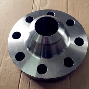
a. Weld Neck Flanges: These flanges have a long tapered hub that is welded to the pipe. They provide a strong and reliable connection, especially in high-pressure applications.
b. Blind Flanges: Also known as blank flanges, these flanges are used to seal the end of a pipeline or vessel. They do not have a bore and are typically used for pressure testing, maintenance, or to close off an unused pipeline opening.
c. Threaded Flanges: These flanges have internal threads that allow them to be screwed onto a threaded pipe or fitting. They provide a secure connection and are commonly used in low-pressure applications or where welding is not preferred.
Each of the aforementioned API flange types has specific size and rating restrictions. Although Type BX flanges cannot be utilised for threaded applications, Type 6B flanges can.
Dissimilarities Between API and ASME Flanges | API vs ASME Flanges
The primary distinction between API and ASME flanges is their pressure ratings, while API flanges are capable of withstanding substantially higher working pressures, ASME flanges cannot. This is because API flanges have greater strength and thickness to withstand the demanding pressure requirements. In addition to Christmas tree and wellhead equipments, API flanges are also found in nuclear power applications, heavy oil refinery systems, bitumen upgraders, and other petrochemicals and acids and are frequently used in their applications.
Due to the stress from the caustic solutions they are exposed to, API flanges are made to withstand corrosion, pitting, and cracking. For refineries that handle materials like oil and explosive gases, and operate at very high pressures and temperatures, API flanges are a great option.
Meanswhile, due to their low pressure ratings, ASME flanges are used for common applications like handling water, steam, air, and gas for industrial processes.
The distinctions between ASME and API flanges are clear, but it’s crucial to remember that both are essential parts of their respective applications. The particular specifications and operational circumstances of the project or piece of equipment in question determine whether to use ASME or API flanges.
Similarities between ASME and API Flanges
While API flanges and ASME flanges may have certain differences in their intended applications and pressure ratings, there are instances where they can be joined together due to certain similarities in their design. This can be advantageous in situations where equipment or piping systems require the connection of components with different specifications.
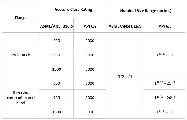
The bolt circle diameter and bolt hole layout are two examples of this commonality. The diameter of the circle that runs through the middle of the bolt holes on a flange is referred to as the bolt circle diameter. The bolt circle diameter and bolt hole designs of API and ASME flanges may occasionally match. This indicates that the flanges have matching bolt holes that line up with one another, making alignment and installation simple.
The flanges as per API 6A and ASME/ANSI B16.5 which share similar dimensions are listed in the below-attached image:
API Flange Dimension Charts
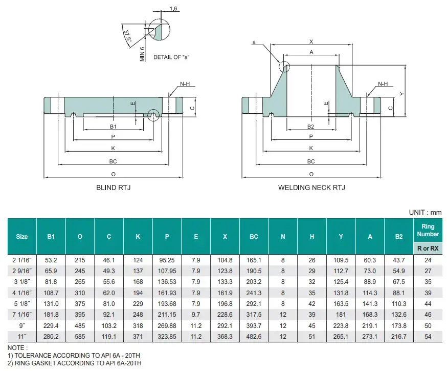
The dimension charts of the most common API flanges are provided below:
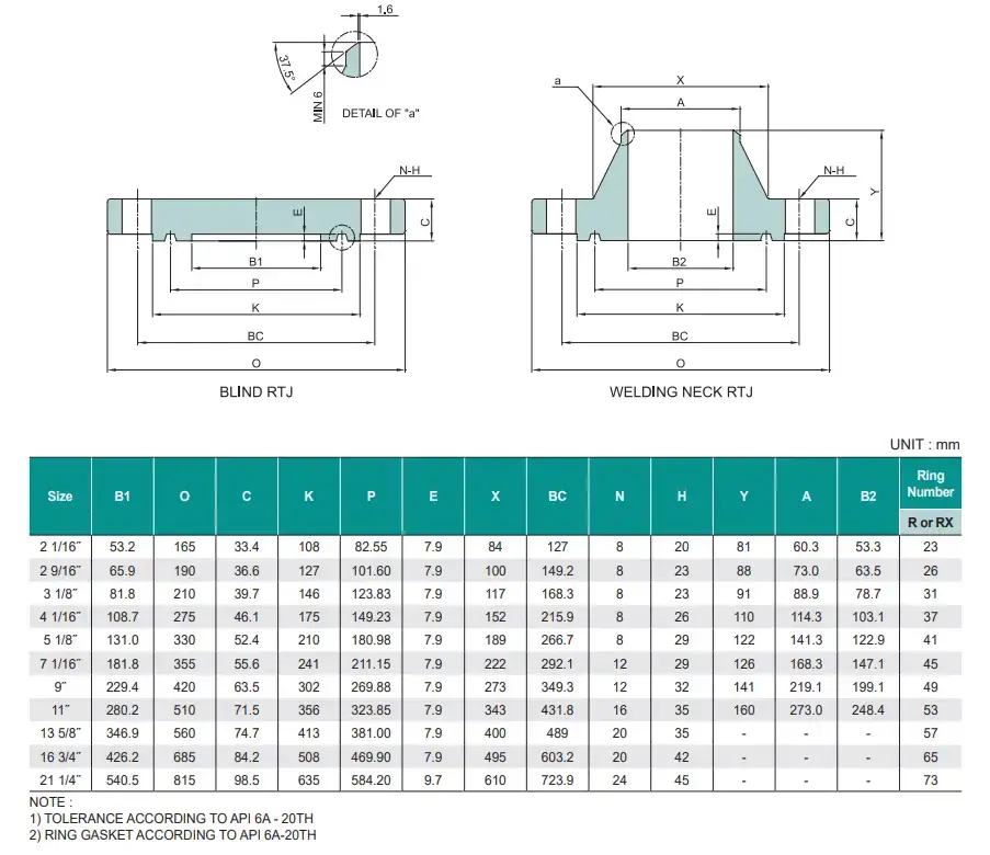
Dimensional Chart for API Flange Type 6B -2000 psi (13.8 MPa)
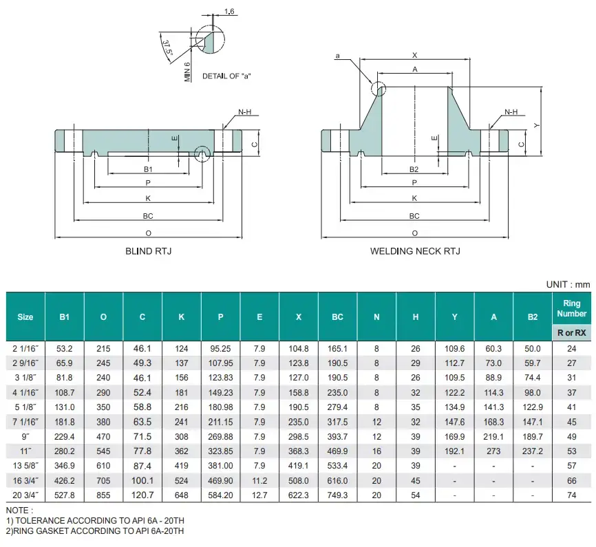
Dimensional Chart for API Flange Type 6B -3000 psi (20.7 MPa)
Dimensional Chart for API Flange Type 6B -5000 psi (34.5 MPa)
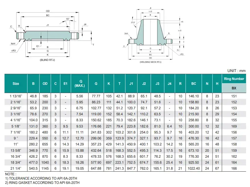
Dimensional Chart for API Flange Type 6BX -2000 psi (13.8 MPa)
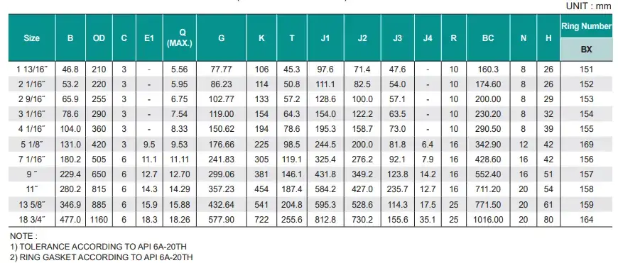
Dimensional Chart for API Flange Type 6BX -3000 psi (20.7 MPa)
Dimensional Chart for API Flange Type 6BX -5000 psi (34.5 MPa)
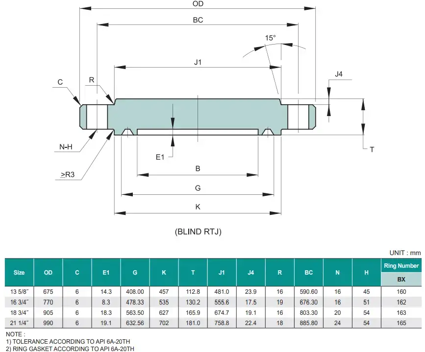
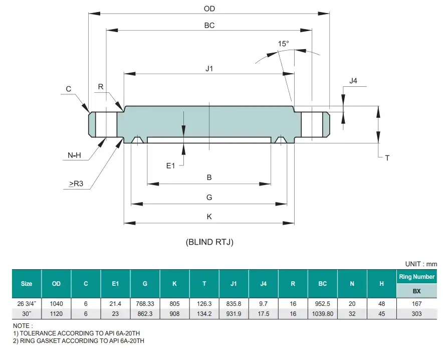
Dimensional Chart for API Flange Type 6BX -10000 psi (69.0 MPa)
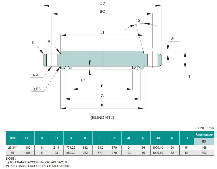
Dimensional Chart for API Flange Type 6BX -15000 psi (103.5 MPa)
Dimensional Chart for API Flange Type 6BX -20000 psi (138.0 MPa)
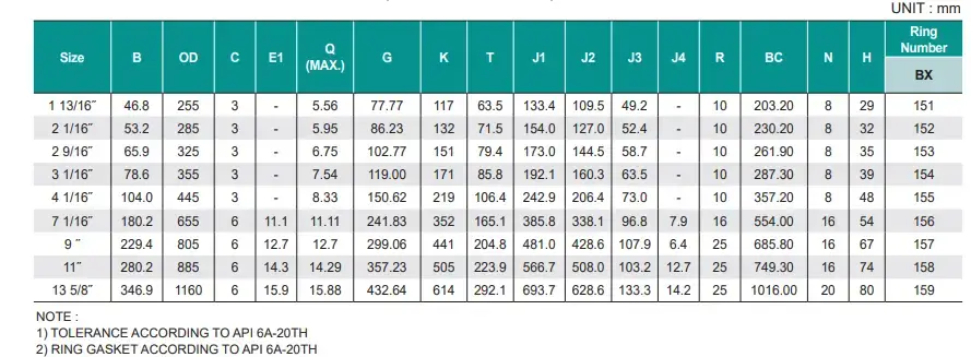
Image Credit for the Dimensional charts for the different API Flanges is http://www.stnhcorp.com/.
API Flange Leakage Testing and Inspection
Flange leakage testing for API flanges is pretty simple with the technology we have in hand nowadays. From a pre-existing stress analysis software, we must obtain the computed axial force and bending moment at the flange face . Thereafter, we need to input the needed curve based on the API TR 6AF standard size and bolt composition stress. Based on the bending moment and bore pressure curves are drawn on those charts to get the allowed axial load (tension). If the computed axial force is less than the curve’s permitted tension, the API flange is declared safe.
Other API Flange Standards
API flanges play a crucial role in the oil and gas industry, providing a standardized and reliable method for connecting pipes, valves, and equipment. In addition to the widely known API 6A specification, there are other API flange standards that provide further guidelines and specifications for specific applications and scenarios. Understanding these additional API flange standards is essential for ensuring safe and efficient operations in the industry.
These include:
API 605: This standard specifies the dimensions and pressure ratings for large-diameter carbon steel flanges (NPS 26′′ and greater).
API 17D: API 17D defines sub-sea wellhead and tree equipment used in offshore drilling and producing activities, including flanges.
Industry experts can benefit from standardised dimensions, pressure ratings, and material requirements by incorporating these new API flange standards into the design and installation processes. This serves to ensure the flanges’ compatibility, dependability, and performance in various oil and gas applications.
Following good installation practises and adhering to API requirements is critical for obtaining best performance and safety. Users can reduce the danger of leakage, improve system performance, and protect the integrity of their oil and gas operations by doing so.
Finally, comprehending the various API flange standards, such as API 605 and API 17D, is crucial for oil and gas professionals. By adhering to these standards, they can make informed decisions regarding the selection, installation, and maintenance of API flanges, ultimately contributing to the safe and efficient functioning of oil and gas systems.


2 thoughts on “Connecting the Dots: Detailed Unveiling the power of API Flanges”