


In piping, a tie-in is when new piping is connected to existing piping. This is done to extend the current system, add branches, or connect it to other equipment. The process can vary depending on the type of piping and its location, and it requires careful planning and execution to ensure safety and effectiveness.
The concept behind piping tie-in is to connect new piping to existing piping in a way that ensures a proper and secure connection while maintaining the integrity of the existing system. The goal is to achieve a seamless integration between the new and existing piping, enabling them to function together as a cohesive unit. It is essential to make tie-ins easy to maintain and repair, while also minimizing the risk of leaks or other issues.
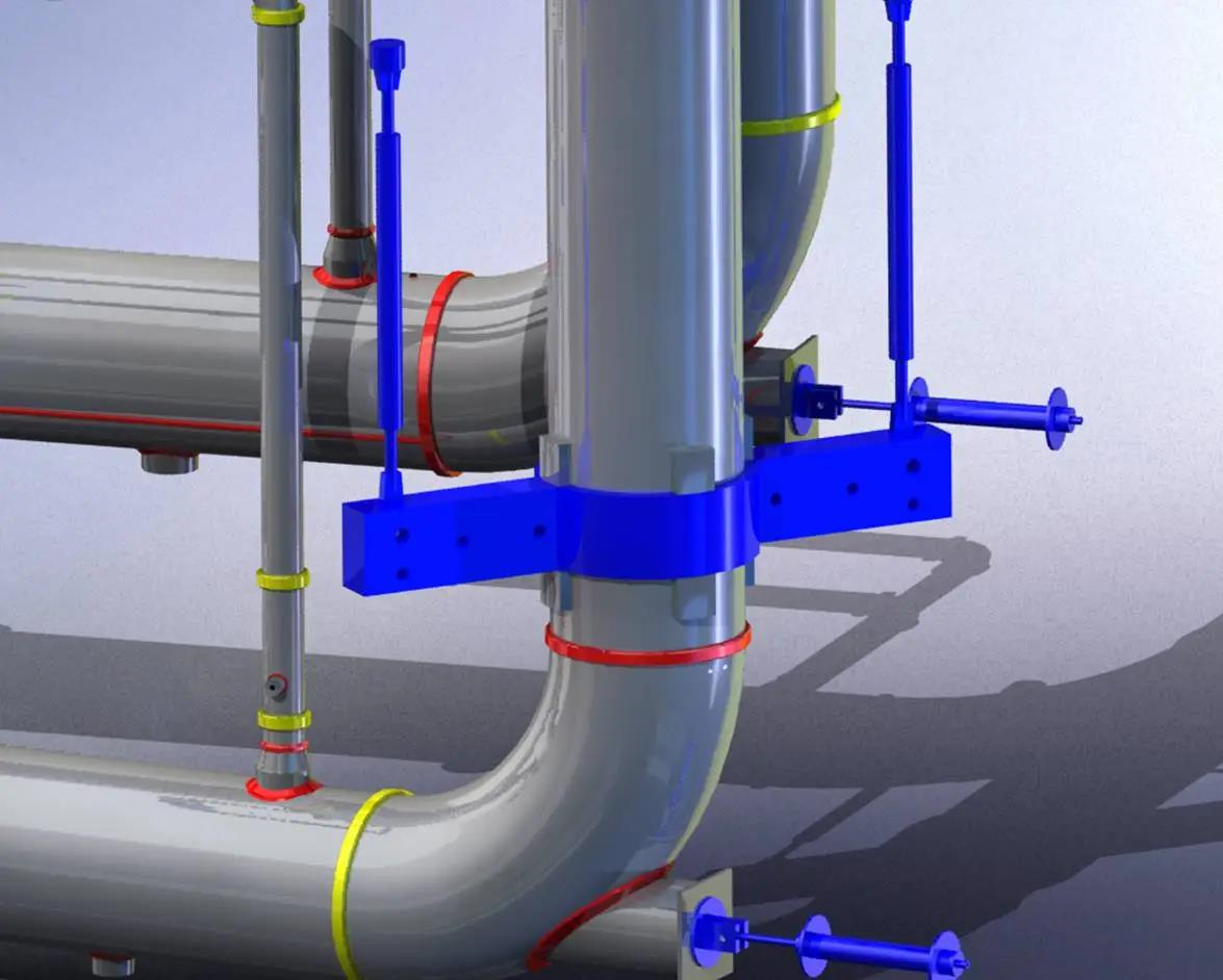
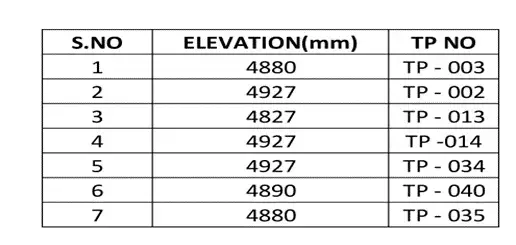
To close tie-in points, blind flanges are commonly used. Additionally, a shut-off valve is installed upstream of the blind flange to provide safe isolation and expansion. Tie-in points are identified and numbered, typically shown in P&ID and Piping Isometrics. A Tie-in table is maintained in the overall General Arrangement drawings and P&ID to help understand the plant interface better. This table includes the Tie-in point numbers and elevations from the design viewpoint. The tie-in list aids in estimating construction costs and scheduling work well before the actual piping design activity takes place.
Types of Piping Tie-ins
There are different types of Tie-in Points, including Plant Tie-In Points and Skid Tie-In Points.
Plant Tie-In Points are used to interface existing plant lines or connect with other process lines from neighboring plants. It’s essential to match the elevations with the existing plant design to ensure proper alignment. The installation of tie-in point flanges or isolated valves should allow sufficient spacing for easy operation and maintenance.
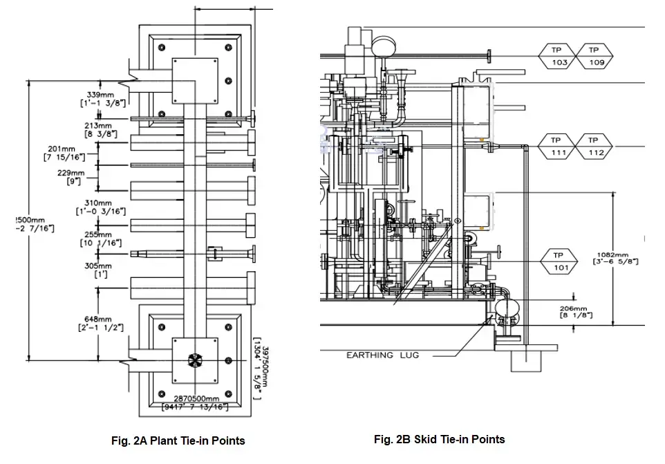
Skid Tie-In Points, on the other hand, are located inside the plant to connect interconnecting piping between different skids and equipment. These tie-in points are strategically placed to enable connections from other skids to be made at a single point, facilitating smooth operation and maintenance.
In terms of connection methodology, there are four types of pipe tie-in connections:
- Buttwelded Piping Tie-in
- Flanged Piping Tie-in
- Threaded Piping Tie-in
- Hot-tapped Tie-in connection

Piping Tie-in Point Design Considerations
When designing piping tie-in points, several considerations are crucial to ensure a successful integration:
- Calculate Flange Loading: Determine allowable flange loading (or tie-in point displacements) as per the applicable standards.
- Accurate Tie-in Locations: Clearly specify tie-in point locations in all directions to avoid conflicts with counter connections.
- Hazard Avoidance: Process engineers should decide on tie-in locations to prevent hazards during operational time.
- Maintenance and Operation: The engineer selecting tie-in locations should consider maintenance and operational aspects. Prepare a tie-in plot plan and seek plant personnel’s input to prevent conflicts.
- Valve and Flange Rating: Consider the valve and flange ratings based on the connecting line size.
- Additional Quantity: Include tie-in items (flanges and valves) as an additional quantity in the piping material take-off (MTO) calculation.
- Physical Site Check: Physically check tie-in locations on-site before preparing the tie-in table.
- Change of Instrumentation: Not all changes in instrumentation or control loops require a tie-in point.
- Drains and Vents: Add additional drains and vents based on the type and location of tie-ins.
- Consider Pipe Supports: Tie-in points should be placed in locations that consider pipe support requirements, as the type of tie-in selected may impact pipe supports.
- Fluid Properties: Process engineers should provide tie-in fluid properties for future equipment designers.
- Suitable Valves: Select suitable shut-off valves (e.g., ball, gate, butterfly) based on the process fluid and pressure conditions.
- Tie-in GA Drawing: Prepare a separate General Arrangement (GA) drawing that shows all tie-in locations in the plant.
- Hot Tapping: In certain conditions where isolating or shutting down the plant process is not possible, consider alternative methods like hot tapping to accommodate line breaks.
Benefits of Piping Tie-in Connections
A piping tie-in point is a location in a pipeline where the pipeline is closed for further expansion or connected to an existing pipeline. These tie-in points are strategically planned during the preparation of P&IDs to cater to future project needs. They are usually situated at the end of plant battery limits on the pipe rack, sleeper, or at the individual equipment ends.
Using piping tie-ins in a system offers several benefits:
- Cost-effective: Tie-ins eliminate the need for new construction and reduce the requirement for new equipment, making them a cost-effective way to add or extend a piping system.
- Increased Efficiency: Connecting new piping to existing piping allows the entire system to function more efficiently and effectively.
- Minimized Downtime: Tie-ins can be carried out with minimal downtime, minimizing disruption to the system’s operation.
- Improved Safety: Properly executed tie-ins can enhance safety by reducing the risk of leaks or other issues.
- Flexibility: Tie-ins offer flexibility as they allow for easy addition or modification of the piping system.
- Better Maintenance: By integrating new piping with existing piping, maintenance becomes easier as any issues can be identified and addressed more promptly.
- Enhanced Integration: Tie-ins create a seamless integration between new and existing piping, leading to improved overall system function and operation.
However, it’s essential to emphasize that proper planning and execution are vital to ensure safety, quality, and efficiency during tie-ins. A detailed method statement, adherence to proper procedures, and a well-trained team are crucial for a successful tie-in.
Piping Tie-in Point Design Considerations
- Calculate allowable flange loading or tie-in point displacements as per the standards before allocating tie-in points.
- Ensure tie-in point locations are accurately specified in all directions to avoid conflicts with counter connections.
- Process engineers should decide on tie-in locations to prevent hazards during operation.
- Tie-in location decisions should be made by engineers with a good understanding of maintenance and operation. A tie-in plot plan should be prepared and checked by plant personnel to avoid conflicts.
- Consider valve and flange ratings based on the connecting line size for tie-in points.
- Include tie-in items like flanges and valves as additional quantities when calculating the piping MTO.
- Physically check tie-in locations on-site before preparing the tie-in table.
- Changes in instrumentation or control loops may not require a tie-in point.
- Add additional drains and vents based on the type and location of tie-ins.
- Place tie-ins considering pipe support locations, as different tie-in types may require varying levels of pipe supports.
- Provide tie-in fluid properties to future equipment designers from the process engineer’s perspective.
- Select suitable shut-off valves (ball, gate, butterfly) for isolation based on the process fluid and pressure conditions.
- Prepare a separate General Arrangement (GA) drawing resembling a plot plan to illustrate all tie-in locations in the plant.
- In situations where isolating the tie-in point or shutting down the plant process is not feasible, consider the alternative method of Hot Tapping to accommodate line breaks. More details about hot tapping on operating lines are covered here.
Benefits of Piping Tie-in Connections
A Tie-In point in a piping or pipeline refers to a location where the pipeline is closed for future expansion or connected to an existing pipeline. These Tie-in points are typically found at the end of plant battery limits, either on the pipe rack, sleeper, or at individual Equipment ends. This connection is made while preparing the P&ID, considering the future requirements of the project.
Using piping tie-ins in a system offers several advantages, including:
- Cost-effectiveness: Tie-ins provide a cost-effective way to add or extend a piping system, as they eliminate the need for new construction and reduce the requirement for additional equipment.
- Increased system efficiency: By connecting new piping to existing pipelines, the entire system can operate more efficiently and effectively.
- Minimized downtime: Tie-ins can be carried out in a manner that minimizes system downtime and disruption to its operation.
- Improved safety: Properly executed tie-ins can enhance safety by reducing the risk of leaks or other issues.
- Flexibility: Tie-ins allow for easy additions or modifications to the piping system, providing flexibility as project requirements change.
- Better maintenance: Connecting new piping to existing lines makes the entire system easier to maintain, as any problems can be identified and addressed quickly.
- Enhanced integration: Tie-ins ensure a seamless integration between new and existing piping, improving the overall functioning and operation of the system.
However, it’s essential to emphasize that proper planning and execution of tie-ins are vital to ensure safety, quality, and efficiency. The use of a detailed method statement, adherence to proper procedures, and a well-trained team are critical to achieving successful tie-ins.
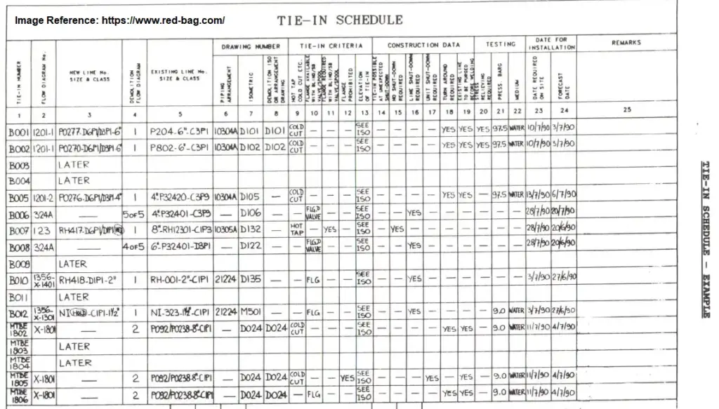
Piping Tie-in Schedule
A piping tie-in schedule is a detailed plan created by process engineers to manage and track a piping tie-in project. This document outlines the tasks to be completed, required resources, and the timeline for each step. It includes milestones, deadlines, and contingency plans for any unexpected challenges. Safety and quality assurance plans, as well as inspection and testing requirements, are also included. The schedule serves as a guide for the project team and stakeholders to monitor progress, address potential issues, and ensure that all tasks are carried out efficiently and on time. It plays a crucial role in coordinating different activities and ensuring a successful piping tie-in.
Safety Features for Pipe Tie-in Connection
- The tie-in schedule should clearly specify whether hot work or cold work will be used during the tying-in operation.
- It must indicate if a shutdown is necessary for the tie-in operation to proceed.
- The lines to be removed must be thoroughly isolated, purged, and free from any hydrocarbon before cutting or unbolting.
- The tie-in schedule should be reviewed alongside the tie-in shutdown philosophy for effective planning.
- The requirement for 100% radiography for critical joints must be explicitly mentioned.
- The construction team must ensure that the existing line is properly isolated, depressurized, and free from hydrocarbon before unbolting. Verify that isolation valves are securely closed.
Piping Tie-in Procedure
A piping tie-in procedure is a step-by-step guide that outlines how to safely and effectively connect new piping to existing piping. It includes details about the equipment, materials, and techniques to be used. Safety precautions, inspection, and testing requirements are also included.
The procedure involves the following steps:
- Planning: Identify the scope of work, gather necessary information and drawings, and determine required resources.
- Preparation: Clean and prepare existing and new piping, and install necessary supports.
- Tying-in: Connect the new piping to the existing piping using methods like cutting, welding, or flanging.
- Testing and Inspection: After completion, test and inspect the system for proper functioning and detect any issues.
- Post-tie-in: Clean up the work area, restore the site and equipment, and update records or drawings.
Before starting the procedure, a permit to work and safety measures should be in place. Conducting a risk assessment to identify and mitigate hazards is essential.
Installation of Piping Tie-in
The installation of piping tie-in involves several activities that are performed in a specific order:
- Tie-in Preliminary Works:
- Notification from the Company about the tie-in project.
- Pre-fabrication of the tie-in spool, which is the connecting piece between the new and existing piping.
- Non-Destructive Examination (NDE) and hydrotest of the tie-in spool to ensure its quality.
- Ultrasonic Testing of the existing tie-in line to check its integrity.
- Excavation and foundation installation if required for the tie-in.
- Tie-in Execution Works:
- Positive Isolation from the Company to safely disconnect the relevant section of the existing piping.
- Blinding the gas-free line to prevent any gas flow during the tie-in process.
- Cold cutting and installation of the tie-in spool to connect the new piping.
- Welding, NDT, and hydrotest of the tie-in to ensure a secure and leak-free connection.
- Line blowing and drying to remove any debris or moisture from the newly connected piping.
- De-blinding and handover to the client for their approval and acceptance.
3. Touch-up and painting:
- Touch-up and painting of the tie-in area to ensure a neat finish.
- Removal of scaffolding and housekeeping to leave the site clean and safe.
- Handover of the tie-in to the operation team/company for its intended use.
Following this well-organized procedure ensures a successful and safe piping tie-in installation.
Piping Tie-in Method Statement
A piping tie-in method statement is a detailed document outlining the safe and efficient procedures for connecting new piping to existing piping. It includes the following information:
- Introduction: An overview of the tie-in’s scope and objectives.
- Equipment and Materials: A list of the tools, equipment, and materials required, including safety gear.
- Procedures: Step-by-step descriptions of the methods used to connect the new piping to the existing piping.
- Safety Precautions: Measures taken to ensure the safety of workers, including handling potential hazards.
- Inspection and Testing: Details about post-tie-in inspections and tests to meet required standards.
- Quality Assurance: Procedures to ensure the work is done to the necessary quality standards.
- Emergency Procedures: Plans for handling accidents or incidents during the tie-in process.
Before starting the tie-in, the method statement must be reviewed and approved by relevant personnel, such as safety officers and project managers. This ensures a safe and successful piping tie-in.