


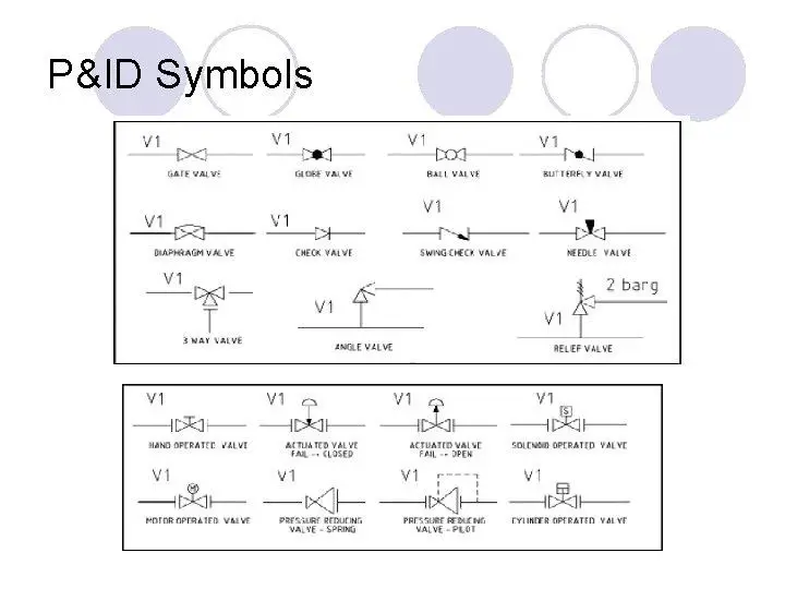
When it comes to oil and gas projects, the process Piping and Instrumentation Diagrams (P&ID) stands as a paramount multidisciplinary document. Piping designers heavily rely on this diagram for crucial information during the installation of a piping system. P&IDs contain a wealth of piping details, serving as a comprehensive road-map for designers. However, amidst the abundance of information, certain terms can bewilder piping engineers and designers. In this article, we will demystify some of these commonly perplexing P&ID terms, providing clarity and understanding to professionals in the field.
This article aims to shed light on four commonly used terms:
- No Pockets,
- Free Draining,
- Slope, and
- Gravity Flow
In this article, through practical examples, we will explore the meaning and requirements associated with each term, offering a comprehensive understanding of their significance in the design of piping systems.
No Pocket
In the realm of Piping and Instrumentation Diagrams (P&IDs), the term “NO POCKET” signifies the absence of liquid pockets within a given pipeline. To prevent the formation of vapor pockets, the note on the P&ID will specify “NO VAPOR POCKETS” when necessary.
When a line is designated as “NO POCKET,” it means that any elevation changes in the line will either be strictly vertical upward or strictly vertical downward, but not a combination of both. This design approach ensures the smooth flow of liquid within the piping system, minimizing the risk of liquid accumulation and associated operational challenges.
Pipe Pocket
In the realm of piping systems, a “pipe pocket” refers to a specific section of a pipe that lacks self-draining capabilities due to its layout or orientation. Essentially, this means that the design of the pipe inhibits the natural drainage of liquids from that particular section.
Pipe pockets can pose significant challenges as they can lead to the accumulation of liquids, resulting in operational issues, maintenance difficulties, and potential hazards. It is crucial for piping engineers and designers to identify and address these non-self-draining sections to ensure the efficient and safe functioning of the overall system.
Origins of Pockets in Piping Systems
- During piping layout, pipes encounter several obstructions, which include structure, equipment, other piping, etc, and may need to change elevation.
- Valve accessibility
- Expansion loop
In order to tackle these challenges effectively, engineers employ strategic solutions such as proper routing to avoid obstructions, careful planning of elevation changes to maintain system functionality, placing valves at convenient locations for easy access, and incorporating expansion loops to mitigate the effects of temperature variations. By addressing these aspects during the piping layout phase, engineers can optimize the design, ensuring a well-functioning and accessible piping system.
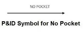
P&ID representation of No Pocket
In Piping and Instrumentation Diagrams (P&IDs), the presence of a “no pocket” condition is typically indicated using a specific symbol— an arrow. This arrow signifies that the section of the piping system it is associated with is designed in a way that prevents the accumulation of liquids or the formation of pockets.
Applications of No-Pocket
The “no-pocket” design approach in piping systems finds various applications across different industries. Here are a few typical scenarios where the implementation of a no-pocket configuration is crucial:
- Two-phase lines: In situations where a mixture of gas and liquid flows through a pipeline, it is essential to avoid any liquid pockets to prevent disruptions in flow and ensure efficient transportation.
- Compressor suction line: To maintain a consistent suction pressure and prevent the accumulation of liquids that could damage the compressor, the suction line should be designed without any pockets.
- Column overhead vapor lines: In distillation or separation processes, vapor lines connected to column overheads must be free of liquid pockets to maintain optimal operation and avoid potential equipment damage.
- Vapor balancing lines: When balancing the vapor flow between different process units or vessels, a no-pocket design is employed to ensure even distribution and prevent any undesired liquid accumulation.
By implementing a no-pocket design in these and other relevant applications, piping engineers ensure the safe and efficient functioning of the overall system, minimizing operational issues and maximizing productivity.
Examples of No-Pocket Lines
Let’s explore a few examples that demonstrate the concept of no-pocket lines in different scenarios:
- Column overhead vapor line: In the context of the column overhead vapor line connected to the overhead condenser, it is essential to ensure that no liquid pocket exists. This serves as the minimum requirement in its design. The presence of entrained liquid in the column overhead vapor can accumulate within a liquid pocket, obstructing the free flow of vapor by blocking the flow path. Detecting this liquid accumulation may prove challenging until operational issues like flooding or deviations in product quality arise. To mitigate such risks and avoid dependence solely on signals and low point draining, engineers carefully route the piping to prevent any liquid accumulation. This is why the notation “NO POCKET” is indicated on the P&ID for the column overhead vapor line.
- Two-phase flow line: Process engineers often include a note on the P&ID requesting support for two-phase flow in the design of such lines. Their objective is to minimize the occurrence of slug flow regimes within the two-phase flow, as these can result in severe pressure fluctuations and vibrations. To maintain stable flow conditions, it is crucial to design the two-phase flow line without any pockets. Liquid accumulation in pockets can promote unstable flow behavior. Engineers aim to prevent pockets in order to ensure a continuous and stable flow of the two-phase mixture.
- Pump suction line: While it is not typically specified on the P&ID, it is important for the design of the pump suction line to avoid any high-point vapor pockets (NO VAPOR POCKET). The absence of vapor pockets in the suction line is vital to ensure smooth pump operation. Vapor pockets can lead to issues like cavitation, which adversely affects the pump’s performance and can potentially cause damage.
By considering these examples and implementing a no-pocket design philosophy, engineers create efficient and reliable piping systems that promote optimal flow conditions, mitigate operational upsets, and enhance overall system performance.
Free Draining
When referring to piping systems, the term “free draining” indicates that the line is configured with downward elevation changes, allowing the effortless drainage of undesired liquid. It strictly prohibits the existence of any liquid or gas pockets within the line. The primary objective of a free draining design is to ensure that no stagnant liquid accumulates, promoting smooth and efficient fluid flow. It is important to note that a free draining line may or may not incorporate slope, as the inclusion of slope depends on specific design considerations and project requirements.
In the realm of piping systems, the term “free draining” signifies a design approach where a line does not require a slope, but it must be devoid of any pockets. When a “FREE DRAINING” note is specified towards equipment or a low point, it indicates that there is an intentional flow of undesirable liquid towards that lower point. This ensures that liquid accumulation is minimized and promotes effective drainage.
Furthermore, a “FREE DRAINING” note with a specific direction is typically used to empty or clean the line by removing any undesirable liquid buildup. It’s important to note that the direction of the main process fluid flow may or may not align with the direction specified for “FREE DRAINING.”
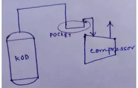
Let’s consider the example of compressor kickback lines. To avoid any hindrance in the kickback operation caused by liquid accumulation, it is essential to ensure a “free draining” configuration.
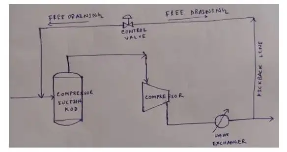
In the case of the vapor kickback line, which primarily carries vapor from the compressor discharge side to the suction side, it is necessary to design the line as free draining. Upstream of the control valve, the line should be free draining towards the inlet line of the suction knockout drum (KOD). Downstream of the control valve, it should be free draining towards a low point in the discharge line.
To achieve this, one approach is to elevate the kickback valve above the maximum liquid level in the drum. By doing so, any liquid that may enter the kickback line can be effectively drained without obstructing the kickback operation.
By ensuring a free draining design for the compressor kickback lines, engineers can maintain unobstructed flow, promote operational efficiency, and prevent potential issues that could arise from liquid accumulation.
P&ID representation
The P&ID symbol for free draining is similar to the No pocket P&ID symbol. Here also the term No Pocket is mentioned above the arrow.
Applications of Free Draining:
PSV inlet/outlet line, Dead leg, Compressor suction line should be free draining towards suction KOD, Compressor kickback line, etc.
Several examples demonstrate the application of free draining lines in different scenarios. Here are a few notable instances:
- Relief valve inlet line: The inlet line of a relief valve should be designed as free draining, directing any liquid towards the protected equipment or the pipe header where the relief valve is installed. Although the relieving fluid flow goes upward and is discharged through the pressure safety valve (PSV), any liquid present in this line should be free draining towards the equipment to prevent liquid accumulation that could impede the relief operation.
- Relief valve outlet line (tail pipe): The outlet line of a relief valve, often referred to as the tail pipe, should also be designed as free draining. The line should allow liquid to drain towards the flare header or flare knockout drum (KOD), as illustrated.

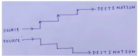
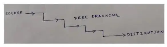
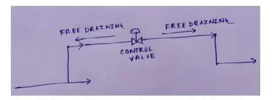
- Dual-section free draining line: In certain cases, a line may consist of two sections that are both designed as free draining, each towards a different direction or destination. This configuration ensures effective drainage of any liquid present in the line, as depicted.
- Compressor suction line: The compressor suction pipe should be designed as free draining, directing any liquid towards the suction knockout drum (KOD) or a low point in the suction line. This design prevents liquid accumulation and promotes smooth flow in the suction system.
By implementing free draining requirements in these various scenarios, engineers optimize the performance and reliability of the piping system, reducing the risks associated with liquid accumulation and ensuring efficient operation.
Slope
In the context of piping systems, the slope refers to a change in the line’s elevation. Typically, slope requirements indicate a consistent downward direction for elevation changes. The specific slope requirements are often denoted on the P&ID using symbols or graphical representations.
These symbols convey the need for a downward slope to ensure proper drainage, prevent liquid accumulation, and facilitate the smooth flow of fluids within the system. By incorporating the appropriate slope in the design, engineers ensure that any undesired liquids can effectively drain out of the piping system, promoting efficient operation and minimizing potential operational issues.
Therefore, slope indications on the P&ID play a crucial role in guiding the proper layout and installation of the piping system, ensuring optimal performance and functionality.
P&ID Symbol for Slope
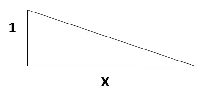
The slope in a piping and instrumentation diagram (P&ID) is visually represented using symbols, as depicted above. In this representation, the unit of measurement for the slope, denoted as X, is the same as 1, indicating a consistent ratio.
Commonly, slope requirements are expressed as “SLOPE is mm:mm,” specifying the ratio between vertical distance (mm) and horizontal distance (mm). For example, a minimum slope of 1:500 is typically required for the Flare main header, while a slope of 1:200 is required for Flare sub-headers.
By defining the appropriate slope ratios on the P&ID, engineers ensure that the piping system is designed to allow proper drainage, prevent liquid accumulation, and maintain the desired flow characteristics. The slope representations on the P&ID provide crucial guidance for installation and construction, ensuring the efficient and effective functioning of the piping system.
Typical Applications of Slope
Several types of lines in piping systems typically require the incorporation of slope. These lines include:
- Flare main header: It is used for collecting and transporting flammable gases for combustion, generally requires a minimum slope to ensure proper drainage and prevent any potential accumulation of liquids.
- Flare sub-header: Similar to the Flare main header, Flare sub-headers, which distribute gases to individual flare stacks, often necessitate a designated slope to facilitate effective drainage and maintain optimal system performance.
- Drain header: These are responsible for collecting and removing unwanted liquids or drainage from different parts of the system, commonly employ slope to ensure smooth flow and prevent stagnant liquid pockets.
- Storm-water channel: These have been designed to manage and direct rainwater or runoff in industrial settings, typically incorporate slope to enable efficient water flow and prevent water pooling or flooding.
By incorporating the appropriate slope for these lines, engineers ensure that liquids or water are effectively drained, minimizing the risk of blockages, system inefficiencies, and potential operational issues. It is crucial to consider these slope requirements during the design and installation of the piping system to maintain its functionality and optimize performance.
Gravity Flow
Gravity flow refers to a system where the downstream elevation of a fluid flow never exceeds the inlet elevations. Unlike free draining, gravity flow lines may contain pockets, allowing the fluid to flow naturally due to the difference in elevation.
P&ID Symbol for Gravity Flow
In Piping and Instrumentation Diagrams (P&IDs), the symbol for gravity flow is represented by combining the gravity flow requirement symbol with the free draining requirement symbol. This indicates that gravity flow is specified above the arrow symbol.
Applications of Gravity Flow
Gravity flow finds application in scenarios where a stacked design is implemented, such as having a column at the bottom, an exchanger (reflux condenser) at the top, and a reflux drum in between. In these configurations, pumps are typically not used for the reflux flow to the column. Instead, the elevation difference allows the reflux to flow by gravity from the drum to the column. Gravity flow is indicated in such cases, highlighting the reliance on the natural elevation difference for fluid movement. It is important to note that gravity flow is distinct from free draining.
While free draining is primarily used for cleaning purposes, gravity flow occurs due to the inherent elevation difference between the source and destination, enabling the process motive fluid to flow without the need for pumps.
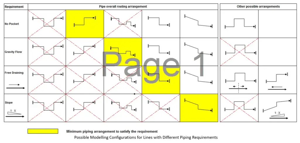
Image below depicts some of the acceptable piping arrangements that can be used by piping designers for the correct interpretation of P&ID piping requirements into the 3D model.


2 thoughts on “P&ID: Understanding Slope, Free Draining, Gravity Flow, and No Pocket”